PoppyUPC - first results

Hi all!

It’s been a while since our last update. This is the project that was presented here, and it was separated to two topics, the mechanical and the electronics part. Here we will present the first version of the PoppyUPC platform (new name, no more Poppy_Essaii).

As a reminder, the idea was to modify cheaper RC servos to make them at least as good as the Dynamixel in order to reduce the price of the Poppy Humanoid robot. The main goal was to create a platform that can be used to study bipedal walking algorithms and for that reason, only the lower part of Poppy Humanoid was considered (two legs). Even though our hope was to try also to make the platform walk, it was impossible to achieve that due to lack of time.

Electronics parts

The motors that were modified are from Hitec and more specifically the model HS-7954SH. All the original electronics parts were removed and a new PCB board was designed in order to host a motor driver, a magnetic encoder (position sensor) and an arduino micro-controller (uC). The result is shown in the next photo (the magnetic encoder is on a “daughter” board that is mounted underneath the “main” board that is shown),

Some details about the parts of the control system of each motor.

The driver can output up to 8A (more than enough), undervoltage shutdown, thermal shutdown, cross-conduction protection and most important, a current sense output. Therefore, with that choice, we already have one feedback signal from the motor. The driver also provide two diagnostic pins to inform the user which of the protections was activated.

The position sensor is the second feedback signal. The magnetic encoder is the AS5145 from AMS and I think is the same as the one that Dynamixel motors are using. Even if it’s not, it also has 12bit resolution (4096 ticks - 0.088 degrees). This sensor needs a magnet to be placed on the output shaft of the gears system. The original system had a potentiometer to read the position that it had to be placed in the same manner. It was easy then to just print a small piece with the same shape as the potentiometer and place the magnet there.

Finally to interact with the driver and the sensor, an arduino (UNO) uC was embedded. The reason of that choice is obvious. The community and the knowledge base of the arduino it will attract more users. We did a small modification here too. We used a 20MHz crystal instead of the standard (for UNO) 16MHz one, in order to boost by 25% the speed of the controller. As in most cases of engineering, there was a trade-off to achieve this as it will be explained later in the communication part. To read the encoder, the spi port was used. This resulted to a reading that last just 60us - quite fast. A timer’s output is producing the PWM signal for the driver, and two GPIO pins control the direction (or braking) of the motor. An analog pin is used to read the current sensor of the driver. Finally two more GPIO pins were used to read the diagnostics from the driver.

Communication

What’s the point to have an arduino embedded to your motor if you are not able to re-program it. This feature that we wanted to include is what we think the biggest advantage over the Dynamixel motor. It was also the decision factor of which type of communication to use. The choice was between the I2C port and the UART port. To upload a sketch though, you can either use an ISP programmer or a FTDI programmer. The ISP needs 4 cables for that when the FTDI 3 cables and a bootloader. Since the amount of cables that go out of the motor is huge issue, the UART+FTDI option was chosen. But since we are using a 20MHz arduino , a new bootloader was needed.

So in the end, with the addition of a new bootloader and a new board entry in the arduino IDE, the user is able to upload sketches to the motor the same was as it uploads sketches to the arduino UNO board. Just click the upload button. Both the rx and tx pins are exposed as well as the reset pin that is needed during the uploading process. The only external hardware that is needed is the FTDI programmer. In the following photo is shown a typical choice that was bought from the local electronics store for 5 euros.

This chip connected to the PC with a USB cable and with one motor with rx/tx pins results in a typical PC-usb-arduino configuration. Which means that the user can also use the serial terminal of the arduino IDE.

To add all the motors on the same network, the RS485 protocol was used. The maximum baud rate though is at 500000 bps (compared to the 1Mbps of the Dynamixel motors). The reason for that is the 20MHz crystal (the trade-off we talked about at the electronics part. A custom library (basically not a library just a couple of functions) was used to handle the incoming and outgoing data in a proper (for the control loop) way. With this ‘library’, if the user is not interested to upload a sketch again, it can use the same configuration as the dynamixel motors (rx and tx pins connected to each other) without any additional external hardware (buffers, NOT gate etc) and of course the USB2Dynamixel adapter.
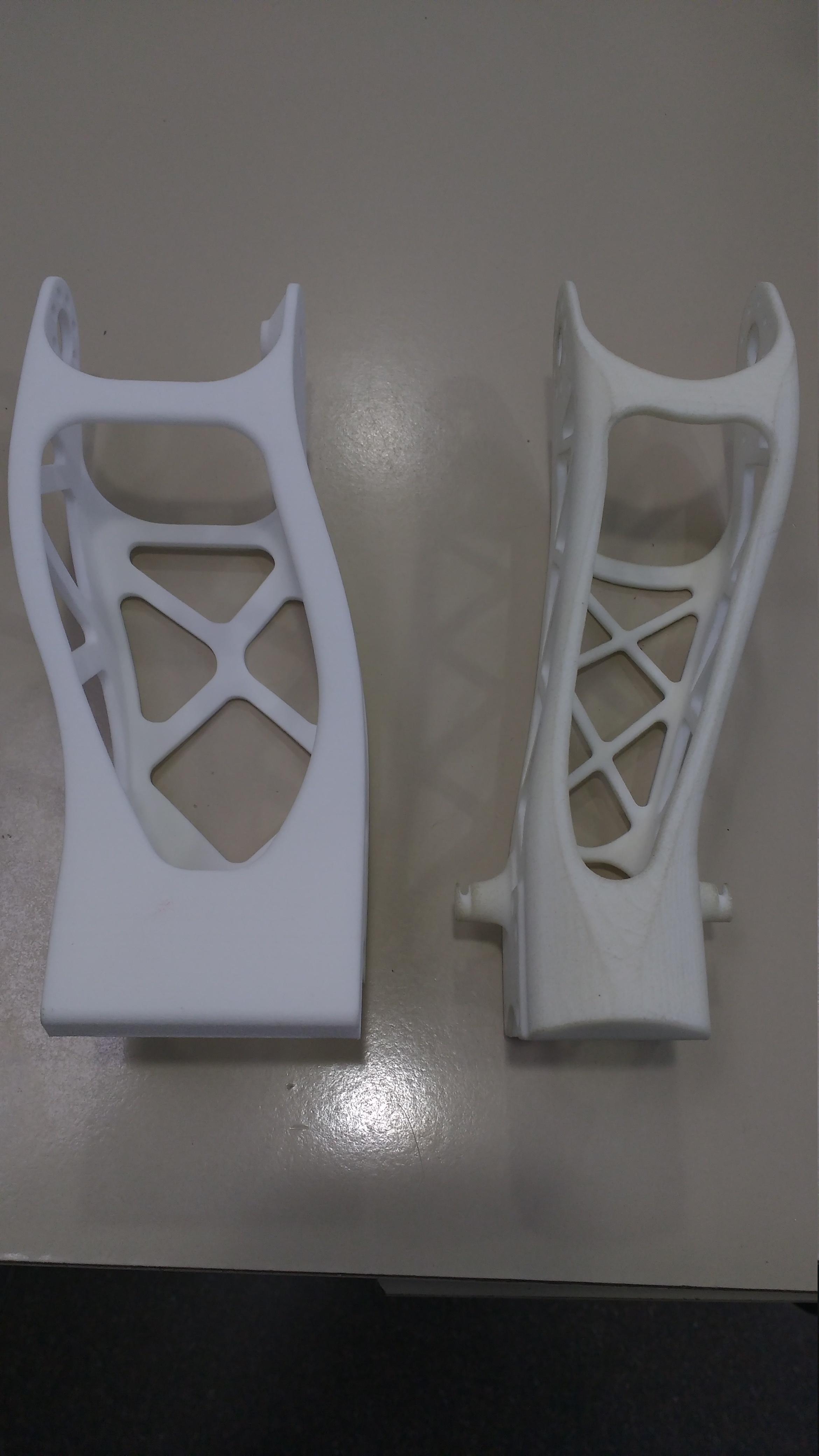
Comparison

The following image shows the comparison between the two motors.

One of the disadvantage of the modified Hitec motor compared to the Dynamixel ones, is the number of cables. The Hitec motor needs 6 cables in total (7.5V, 5V, GND, Rx, Tx, Rst) compared to the 3 from Dynamixel. The 5V cable is there because of lack of space on the board to place a voltage regulator. In the future version of the board though, there will be a regulator so overall in total it will be 5 cables. The Rx and Tx pins are used for the communication between motors and along with the reset pin for uploading new sketches.

As for the performance, both motors can produce similar torque but the advantage of the modified Hitec motor is that the user can upload its own controller such as, optimal controller, H-inf etc. Of course, due to the lower supply voltage, Hitec will need more consumption than the Dynamixel.

Controller

Various controllers were designed for the motor. Starting from simple PID controllers either for position or velocity control. An observer was also designed to ‘observe’ the states of the motor (velocity, current) instead of measuring them (noisy signals). Finally, a colleague used a disturbance rejection observer to close the loop and control the position of the motor.

Main Computer Unit

The main computer unit was chosen to be an Odroid-C1 but the system was also tested with the XU4 model. The main reason for this choice (instead of Raspberry Pi) is the easy to install (and use) ROS. I have been working with ROS on Odroid during the last year and I have seen no difference with the ROS installation on my desktop computer. As it well known, both Odroid boards have two exposed UART ports on their pins. Because of that, the user has various options of how to connect the motors to Odroid. Someone can connect the motors of one leg to the first Odroid port and the motors of the other leg to the second port (it will loose the option of uploading sketches though) reducing the load of the lines to half. Or he can connect all the motors to a USB port of the Odroid board through an FTDI chip, install arduino IDE on Odroid, and communicate and upload sketches with the same configuration (even remotely- ssh). With this last configuration, he can also connect the motors to a desktop pc by just taking the usb cable from the odroid and use it on the pc.

ROS

A ROS package was created in order to communicate with the motors. In fact this package is using a C++ library (also created by us) that is responsible for the communication, and it uses the ROS ‘benefits’ to publish all the information in ROS topics. Any other ROS package can then subscribe to this topics connecting that way the platform to the ROS world.

3 Likes

Mechanical parts

The main problem with the new motors is the lack of mounting points. So the first we did was to print some parts, mount them to the motor case so that it will look like that,


And two more images,


These four screws that hold the two printed parts together add more weight to each motor which is a disadvantage compared to the Dynamixel motor. The other disadvantage has to do with the original Poppy design. The new motors are wider than the Dynamixel and therefore the rigid parts had to be modified as well.

Apart of the modification that was just mentioned, we also added an extra joint for the ankle movement on the lateral direction and we changed the position of the hip joint. We wanted to maintain the cost of the whole platform as low as possible therefore the new parts are easily printed even by low cost 3D printers (FDM). Therefore there is no bended thigh anymore, even though we realize the importance of it in a bipedal algorithm. And to prove that, there is also a design for the bended thigh that was printed to a external service (90 euros per piece approximately). The next photo shows the difference between our two designs and the next one the difference between our design and the original poppy design.


Finally, the platform assembled (apart of the cables -I will write a different post of how we handled all these- ) with the straight thighs (no money to print a second bended thigh :sweat_smile:),


The reason for that metalic stick is to push the Center of Mass (CoM) closer to the hip, where the human’s CoM in order to make the -future- algorithms more realistic and more adaptable to a fully humanoid robot.

Sensors

At the bottom of each foot, there are 3 FSR sensors. Originally there was a hope that with these three -noisy- sensors we would be able to have a rough estimate of the Center of Pressure but this idea was abandoned after the very first test results. Nevertheless, the sensors have their use, as they indicate at which state is the biped at any point (single support or double support), assuming flat terrain. Another custom board was design for each foot to host an arduino that reads these sensors and is connected to the same network as the motors. The next photo show the way we attached these sensors,

Finally, the IMU unit that was used is the Razor IMU, where the [AHRS] (https://github.com/ptrbrtz/razor-9dof-ahrs/wiki/Tutorial) code was uploaded. This code is giving the Euler angles directly and is quite efficient fast and accurate therefore we didn’t spent any time to design our own filter (not that we had any time :slight_smile:). The only drawback is that the Serial port is configured to 57600 baud rate, therefore to connect it to the Odroid board, another FTDI board is needed so that another port will be opened configured at that speed (motors and FSR are communicating at 500K bps).

2 Likes

Hi again!

Recently we have finished the first part of the simulation. In this part we created the URDF description file of Poppy_UPC.

The first step was to design a basic body made of boxes, this way let us check easily mistakes made:

Then we started exporting the meshes from SolidWorks (.stl format) and the physical parameters (centre of mass, weight and inertia matrix) to include them in the URDF file. Finally we obtain this :open_mouth::

Our next step will be create the collision meshes, spawn Poppy_UPC in Gazebo and start working with pyshics!

Stay tuned!

4 Likes

Great work dude! Actually I have got two questions on the ROS side communication stuff since I am working a similar project right now.

My first question is that are you using ROS serial arduino package for serial communication? Is that gonna work with FTDI and Uno like atmega chip?

And how do you manage to get the “Daisy chain” feature work (just like Dynamixel)? I am planning to get some max485 chips to work with atmega ucs while I am not sure how that is gonna work.

Thanks!

Cheers,
Lethic

Hi lethic!

Thanks for the good words (even though we are two…dudes :slight_smile: )!

Now about your questions. No we are not using ‘ROS serial arduino’. We made our own C++ library for the communication. The library is using very similar serial word with Dynamixel so that if someone has its own libraries for Dynamixel motors, it would be easy and fast to modify them for our motors.

The FTDI can be used if you have both rx and tx pins exposed. USB-FTDI board-Arduino is exactly the same configuration as the Arduino-UNO board. In fact the old UNO boards had the same exactly chip (now they use a second uc). Now if you can use the FTDI board with ROS serial arduino package… Never tried it, but I don’t see any reason why not.

As for how I connected multiple arduino’s on the main RX/TX lines, you have to isolate the tx pins of the slaves (arduino’s) from the network. Rx pins are inputs and Tx are outputs. You must have only one output pin ‘activated’ at each time. The master Tx is connected with all the Rx pins of arduino’s - everything works here. The tricky part is when the slave wants to respond, as all the tx pins of arduino’s are connected to the Rx line of the master,

There are two solutions (that I know) for that. The one is to use diodes and a pull up resistor. In case the network’s RX/TX lines are ‘HIGH’ when are at idle,

Whenever a slave wants to communicate with the master it starts dropping the line to start creating bits, bytes etc…

The other solution, is to do that by software (like dynamixel). The Arduino chip gives you the option to set the rx/tx pin to tri-state (high impedance) which is what exactly we want. So when the arduino’s are ‘listening’ the tx pin is deactivated and when a slave has to respond, it activate the Tx pin, send the data and again deactivate the Tx pin.

If you connect the RX and TX pins together, then you have the TTL communication that Dynamixel is referring to (don’t understand the name though but anyway). The difference from the slave point of view now is that, when it has to send data, first has to deactivate the Rx pin, then activate the Tx pin and send the data, and flip back to the original state (Rx actiavted - Tx deactivated).

There’s one problem with that though. The same procedure must be followed by the master as well, and the Linux kernel is not providing any viable option. With the FTDI board, there is a trick to activate and de-activate the rx/tx pins but the transition is as slow as 0.5 sec which is of course extremely slow for our purpose. And the same holds if you use directly the tx/rx exposed pins on Odroid. How Dynamixel solved that? I don’t know! :smiley: For sure by hardware (USB2Dynamixel) but I never found the time to investigate it more.

So, I don’t know if there is any benefit to use the max485 chip. Maybe it will help if you have a lot slaves connected to the network? Don’t know. From my experience, I have 12 motors on the network plus 2 arduino’s more that read the FSR sensors so in total 14 slaves running on a loop at 500Hz. The baud rate is at 0.5 Mbps and the master runs on a loop at 50Hz and I rarely see any checksum error.

Hope that helps!
DImitris & Joan (2 dudes :smile:)

Hi Dlmitris & Joan,

Thank you so much for your comprehensive and informative answer! I definitely learned a lot. It seems that you’ve already got some amazing results!

Please correct me if I am wrong. From what I understand, I assume you are using the first solution you mentioned to drive the 14 slaves at 500 Hz, which is to use diodes and pull up resistors to achieve the Daisy chain feature. Actually I got the idea for using max485 chip for communication from Supermodified servo (http://letsmakerobots.com/node/18615) while I am also not sure what is the benefit for using that. I am wondering what kind of communication library I can use if I want to connect the RX/TX of the Odroid to the RX/TX of the Arduinos directly (of course there might be a need for voltage level converter between them). I would appreciate if you could give me some suggestion on that.

Another thing I would like to mention about Dynamixel’s 3-wire “TTL” half-duplex communication is that they used something called 74HC126. More details can be found in this article: http://www.servomagazine.com/uploads/issue_downloads/Unwinding_the_AX12.pdf

Thanks again dudes! :grinning:

Cheers,
Lethic

Hi Lethic,

We use both of the solutions on the same time :slight_smile: The reason was mentioned on the first post. If the user doesn’t want to upload any new sketch then with the same arduino code he can run the motors with 1 cable for communication (as Dynamixel) by simply connecting the rx-tx pins together. Of course on that scenario, he must have a USB2Dynamixel connector.

As for the slaves…The motors have their own control loop and they can handle the incoming data (instruction) and the outgoing data (response) without breaking that loop. That is, the feedback from the motor and the application of the new control signal, take place in a fixed periodic time as any classical control theory suggest. What’s the limitation of the frequency of the loop? That depends on the maximum data that a slave has to handle. For example, the motor has to send back 3 float numbers (12 bytes) plus the time to receive the instruction from Odroid. In our case, the worst case scenario needs around 700us (that is, only for communication). If you want a 1000Hz control loop, you have 300us left, which is more than enough for a simple PID controller. Well, we give our control loop the time to breathe cause we still try different controllers, so we have a control loop that runs every 2ms.

Now, the supernodified, at your link they are talking about 1000Hz loop but on their website they claim a 9,765 KHz control loop which means more or less 0.1ms loop (!!). If that’s accurate, that means that any command you send to the servo it ruins the control loop. For our application this is not acceptable.

So… the motors have their control loop that runs every 2ms and can handle any aperiodic instruction-response. Odroid (ROS) has a loop of 50Hz during which, at minimum it asks all the feedback from all the motors.

Now for your application, I suppose you also want to connect a lot of arduino’s on the RX/TX lines of Odroid. The library is not an issue. You can use the WiringPi for C++ or the [pySerial] (https://github.com/hardkernel/wiringPi) if you prefer Python. Or, you can wait until we make our library open source but I cannot give you any estimation on when that will happen. It’s nothing special though, it uses typical Linux Serial Programming (just as WiringPi).

Finally, for the AX12 and the 74HC126. There is this manual that explains everything in detail (page 7 the one that’s interesting). The circuit is just buffers (74HC126) and a ‘not’ gate. It’s another way to activate the RX pin and on the same time de-activate the TX pin and vice versa. If you don’t want to handle this by software (on the Arduino side) it is also highly recommended. In fact, IF you use the arduino UNO board, you cannot actually deactivate the TX pin!! (there is a resistor in series to this pin that doesn’t allow you to do that). So if the arduinos you want to connect are not standalone, you must use external hardware (74HC126) to achieve “TTL communication”.

Hope that helps,
Dimitris & Joan

Hi Dimitris & Joan,

Thanks a lot for explaining this to me. Sorry I misunderstood your previous answer. So the way you achieve

is basically doing something like this figure below (power line omitted)?

Since you mentioned the FTDI and Odroid’s RX/TX are both too slow for active/de-active transition, so I assumed you are using USB2Dynamixel. But I am not sure if I am correct to put the diodes and pull-up resistor in this figure.

And on the other hand, the way to upload new sketch to the arduino would be something like this:

Thanks a lot for your time again!

Cheers,
Lethic

Hi Lethic,

Sorry, my explanation probably was not that good. We don’t use the USB2Dynamixel cause we want to keep the option to upload sketches (which, trust me, is extremely handy!). So basically I have 3 options

FTDI board

All motors are connected to the rx/tx lines with one pull-up resistor and diodes on slave’s TX line. Plus you have a reset line.

Advantages:

  • You can upload sketches
  • You can use it either on Odroid or on a PC.

Disadvantages:

  • You have 3 cables in total just for the communication.

ODROID GPIO

You can use the serial ports that are exposed on the GPIO pins of Odroid, again with the pull-up resistor and the diodes.

Advantages:

  • No external hardware (no need for FTDI/USB2Dyn.)
  • You can split the load of the lines to the two ports (e.g. left leg on portA - right leg on portB)

Disadvantages:

  • You cannot upload sketches anymore as there is no reset line now.

These two options are shown on the following image,

USB2DYnamixel

The third option, assuming that the arduinos don’t need the 74HC126. No more pull-up resistor or diodes. Rx and Tx are connected to each other.

Advantages:

  • Only one line for communication
  • Can be used either on Odroid or on a PC

Disadvantages:

  • You cannot upload sketches anymore (no reset line)
  • USB2DYnamixel cost around 45 euros last time I checked (compared to the 5 euros FTDI board)

Hopefully now is more clear. :slight_smile:

Dimitris & Joan

Hi Dimitris & Joan,

Thank you sooooooo much!

I would say this is a super clear explanation of the whole thing! I have been googling fragmented knowledge since last year and you really solved all my confusion this time. I guess I will follow your ideas of using FTDI for sketch uploading and Odroid GPIO for controlling, which would be a good practice of serial port programming.

I hope you guys get great success in your next step.

Thanks again!

Cheers,
Lethic

We made a small demonstration for the ROS package in order to check also the generated meshes. Nothing fancy (for now), just reading the position of each motor and ‘visualize’ the movements in RVIZ.

(We still wait for the boards that will help with the cables…)

2 Likes