Actually we work on installation process of poppy robots,
I imagine a way to setup the sc16is7xx driver easily. I will create a .ko for each actual kernel (4.2 or more) revision and put it on a repo as release with a specific name depending on the kernel revision. After that we could link travis to raspberry kernel repository and generate a new .ko release for each kernel revision available.
On the same repo we put a bash script who select the release depending on the kernel revision of the raspberry and setting it up. This script can be called easily with a simple command line and this is not dependant of a complete poppy robot.
In my case it seems to work. If I comment that define and run a make clean and then make I get the 3 warnings during compiling and the ko file is 6552 bytes.
When I put the define back in there are no more warnings in the compilation and the ko file is 24952 bytes - clearly the #ifdef are considered.
Yes, it probably will work. We might also consider putting an EEPROM on the board and certifying it as a HAT. That would mean the drivers will have to be included in the standard distributions for Raspberry Pi. For instance I’ve seen some cards from Adafruit (like the PiTFT 2.8) come with overlays and ko’s in the standard distribution of system. But for the time being precompiling them for each kernel version and using a script to do the installation might be easier. Keep in mind that also the dtb needs to be different (at least the name) for the 4.4> versions (extension dtbo and no “-overlay” in the name).
Have you yet testing it with a 241 on the Dynamixel chain? I hooked it up last night but couldn’t make it communicate. I suspect it’s because of the fact we haven’t set the chip in RS485 mode - so that the RTS pin controls the communication direction. I can’t figure out how that is done through the driver.
@Nicolas here is what I managed about setting up the RS485 mode:
first you need the version 3 of pyserial. Run pip list and check for the version you have installed. If it is 2.x then you need to upgrade - the RS485 support is only included in version 3:
pip install --upgrade pyserial
Then there is a bug in serialposix.py source that will throw some errors. They are fixed in the source but that is not included in the official release. So you’ll need to download the code and replace it in the local distribution package:
In principle after this the chip should be in RS485 mode and the RTS pin should control the direction.
Unfortunately in my case it still doesn’t communicate with the servo. And I have no oscilloscope to test if the RTS pin works fine. Can you check this part?
I was using a AX-12A so the DxlIO is fine. I probably need to look at the connections again.
If you have a crystal available 32 or 16MHz you might also hack the board so that you can also do some performance testing - see how long the packets take to go back and forth. If everything looks fine we’re good to go for the prototype batch.
Don’t forget to change the circuit design to include the IRQ connection before sending the production order.
As @damien mentioned it before , we have the 2 first Hipi prototypes. These boards have been produced by CircuitHub but CiruitHub have failed in the Raspberry connector mounting, they mounted it reversed… I can’t mount it on a RPI for now and reverse this connector is a really tricky thing…
Anyway I start to test each functionality (with wire) of this board step by step :
[] Power conversion => TOO noisy
[*] Audio amplifier
[*] Driver of sc16is752
[*] Apparition of /dev/ttySC0 and SC1
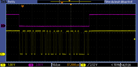
[*] TTL Communication with motors at 1000000
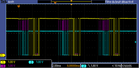
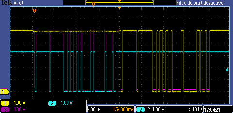
[] RS485 Communication with motors at 1000000
[] IMU
[] Mechanical integration
I will update this topic and check this boxes to keep everybody in touch.
Now I can detect sc16is752 and see /dev/ttySC* but when I send something nothing happend on data side of the ttlmotor connector.
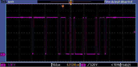
I think I switch the logic direction of RTS…
Indeed, if I switch the RTS logic
With pyserial > 3
import serial
import serial.rs485
ser = serial.Serial('/dev/ttySC0', 1000000, timeout=0.5)
ser.rs485_mode = serial.rs485.RS485Settings(rts_level_for_tx=False, rts_level_for_rx=True, delay_before_tx=0, delay_before_rx=0)
I got something in the output.
Mistake list :
I have mounted the TTL connector reversed because the 3D view on CircuitMaker is reversed and the one pin of robotis is not the 1 pin of the connector but the last one… I will need to make it easyer for users. I plug it on a robot so the 5V push/pull output of the driver has been short-circuited to GND… Hipi continuing to work
I short circuit GND and power input with my oscilloscope, but I’m lucky a 0Homs resistor suicied itself to save the rest of the board
The COUT capacitor of the alimentation work at 4v, so the capacitance could be really bad at 5v… I change it with a bigger capacitorworking at 16V but the output steel crappy. I also try on the second Hipi but it steel noisy. I can catch some 200mv glitch without nothing mounted on the board
I wrote in a post earlier on the 1st of April how the 2G241 should be connected - and I think it was wrong. By default the RTS is low for TX and high for RX (page 33 in manual) so the 2G241 should be used 1A/1Y for TX (active low) and 2A/2Y for RX (active high). This way you don’t need to change the direction in software. It’s more intuitive to use.
If you still have ripples that big you might have some sort of a short on the board. I haven’t checked the oscillator on the power source (that’s why I use the Murata…) but I will look at the calculations. 47uF at the output should be more than enough - although indeed is should be at least at double the output voltage (so minimum 10V).
I mount a Raspberry Pi 3 with a Hipi board on the head of an humanoid robot and I add a screen on it.
The humanoid with a current version of Pypot and a Hipi have an extremely strange behavior! Thank’s to @Pierre we understand why.
In a Poppy humanoid robot we have 2 motors network (1 for legs, 1 for torso). Pypot create 2 threads to manage each UART simultaneously but in reality both use the same device (SPI) and if one of the UARD deice use The SPI driver The other one will be dropped.
@Pierre add a lock rule to avoid this kind of problem, and now it’s working.
We still having some strange things probably due to overheating on the head…